Aluminum PCB Manufacturer Selection: The Mechanical Interface Nobody Declares
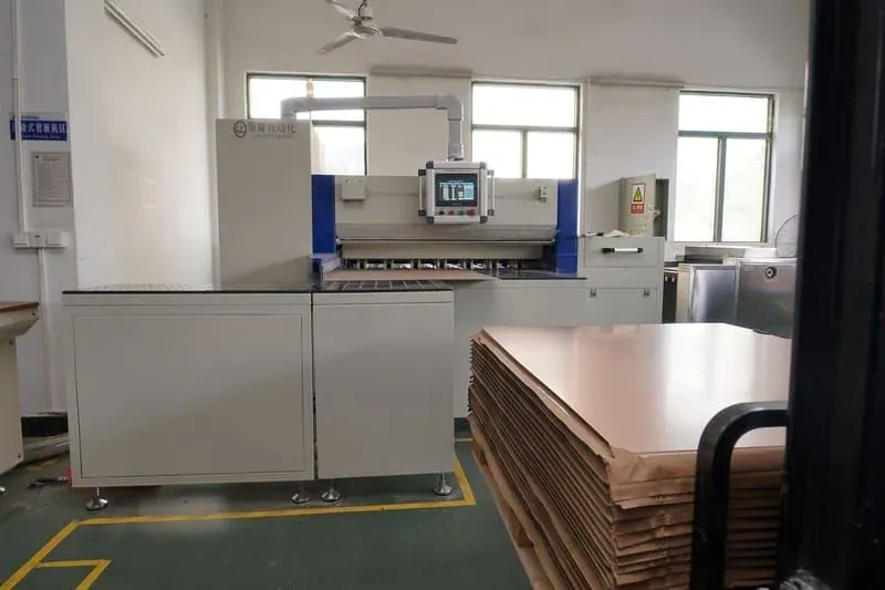
The thermal chain breaks in the last fifty microns
Every aluminum PCB conversation starts in the same place. You compare base material, you compare copper
weight, you compare dielectric layer options, you ask for thermal numbers, and you shortlist suppliers on
what they can fabricate. All of that is useful, and all of it describes the board in isolation.
Then the board arrives, gets bolted to a heatsink or a chassis wall, and the thermal path it was bought for
either exists or it does not. Not because the fabrication was wrong — because the board does not sit flat
against the mating surface, or it sits flat only where the screws are, or the screws cannot be torqued down
without the board rocking on a high corner.
This is the part of an aluminum PCB purchase that almost never gets specified. The board is a thermal
component whose entire function depends on a mechanical condition at its back face, and that mechanical
condition is created by a set of attributes that your RFQ does not mention:
- where the mounting holes are and how big they are
- whether those holes are countersunk, counterbored or plain, and who decided
- how accurately the board outline matches the pocket or bracket it has to drop into
- how flat the back face is, and relative to what reference
- how much the board bows or twists, and whether that is measured free-standing or clamped
- what is actually on the back face — bare metal, solder mask, ink, a protective film, nothing
- how much clearance exists between a grounded screw and the nearest conductor
Notice what these have in common. Not one of them is a property of the laminate. All of them are properties
of the interface. And the interface is exactly what neither party writes down.
The honest version of what goes wrong
The failure mode is unusually clean, and it is worth stating precisely because it explains why it keeps
happening to competent buyers.
You issue an RFQ. It says aluminum base, a copper weight, a dielectric option, a board size, a quantity.
The supplier quotes against exactly that and builds exactly that. The boards arrive, pass incoming
electrical checks, and look correct. Your mechanical team mounts them and finds that torquing the corner
screws lifts the centre, or that one screw hole does not line up with the boss, or that the back face has a
skin of mask where you expected bare metal and the interface material behaves differently than the thermal
model assumed.
Now run the dispute. Did the supplier deliver a non-conforming board? No — every attribute you specified is
in tolerance. Did you order the wrong board? Also no — you ordered a board that matches your design intent.
The gap is not between the order and the delivery. It is between the order and the application. Nobody
breached anything, which is exactly why there is no clean remedy and why these conversations take weeks.
The second-order problem is worse than the first. Because no attribute was violated, the supplier has no
obligation to change anything on the next build. So the same boards arrive again, and your mechanical team
builds a workaround — extra screws, a thicker gap pad, selective shimming — and the workaround becomes
permanent and undocumented. Six months later nobody remembers why the assembly has four screws where the
drawing shows two.
Who declares what: the split that actually holds
The unproductive version of this conversation is "whose fault is flatness." Everyone has an answer and
nothing changes. The productive version assigns each attribute to the party that owns the physical reality
behind it, and fixes the order in which they speak.
| Attribute | Declared by | Must be stated before | Verifiable on arrival? |
|---|---|---|---|
| Mounting hole positions and diameters | Buyer (from the mechanical assembly) | Quotation | Yes — dimensional |
| Hole form: plain, countersunk, counterbored | Buyer, on supplier input about what is producible | Quotation | Yes — visual and dimensional |
| Board outline and edge tolerance | Buyer, as a drawing with a datum | Quotation | Yes, if a datum exists |
| Backside flatness and bow/twist limits | Buyer states the requirement; supplier confirms achievability | Quotation | Only with a stated method |
| Measurement condition: free or clamped | Buyer — this is the one that decides disputes | Quotation | Yes, once stated |
| Backside finish: bare, masked, inked, filmed | Buyer, explicitly, including "bare means bare" | Quotation | Yes — visual |
| Edge burr and deburring expectation | Supplier declares its standard; buyer accepts or overrides | Quotation | Yes — tactile and visual |
| Creepage around mounting hardware | Buyer, from the circuit and the hardware | Before layout freeze | Yes — dimensional |
| Thermal interface material | Buyer (it is an assembly decision, not a board attribute) | Not a board attribute | N/A |
| Torque sequence and fastener spec | Buyer | Not a board attribute | N/A |
Two rows carry most of the value. Measurement condition is the single most dispute-resolving line in the
table, and the one most often absent. And backside finish is the one buyers most often assume rather than
state, because "aluminum base" sounds like it describes the back face. It does not.
Note what the table does not claim. It does not say the supplier designs your mechanical interface, and it
does not make flatness the buyer's problem alone. It says each attribute has one declaring party, and the
declaration happens at quotation — not at incoming inspection, where it becomes an argument instead of a
specification.
Mounting holes: the attribute that looks trivial and is not
Mounting holes get drawn early, by whoever is doing the layout, usually from a mechanical sketch. They then
stay untouched through the entire project because they look like the least interesting feature on the board.
Three things hide in them.
Position tolerance has a datum or it has nothing. A hole dimensioned from the board edge inherits the
edge's own tolerance. A hole dimensioned from another hole inherits only the drilling accuracy between them.
These are different requirements with different outcomes, and they diverge most on exactly the boards where
it matters — large thermal boards where accumulated tolerance across a long span decides whether the last
screw lines up with the last boss. Pick the datum deliberately and put it on the drawing. If the drawing has
no datum, the supplier picks one, and it will be whichever is convenient for its own process.
Hole form is a thermal decision disguised as a mechanical one. A plain hole with a pan-head screw puts
the fastener head above the board surface. A countersunk hole puts it flush, which you may need for
clearance, but it also removes material around the hole and changes how the clamping force spreads into the
board. A counterbore does something different again. Which forms are producible in a metal-backed board, and
with what geometry, is a process question — ask it at quotation rather than discovering the answer after
layout freeze.
Burr at the hole is a flatness problem, not a cosmetic one. A raised burr on the back face of a mounting
hole lifts the board locally off the mating surface, directly under the point where you are applying clamping
force. It is a small defect with leverage. Deburring expectations on the *back* face specifically — not
"deburred" in general — belong in the specification, and they are visible and feelable on arrival, which
makes them one of the easier things to agree on.
Flatness: a requirement with no method is not a requirement
This is where most aluminum PCB specifications quietly fail. A line that says the board shall be flat, or
gives a flatness requirement without saying how it is evaluated, cannot be enforced and cannot be defended.
Four things have to be stated together or the requirement means nothing.
One: what "flat" refers to. Overall bow across the board, local deviation within a small region, twist
between corners, and deviation only in the area that actually contacts the heatsink are four different
quantities. A board can be acceptable on one and unacceptable on another. Say which one you care about —
and if the board only mates over part of its area, say that the requirement applies to that area.
Two: the reference surface. Flatness is always relative to something. Back face against a surface plate.
Front face. A plane through three specified points. Without a stated reference, you and the supplier will
each pick one, and you will pick different ones.
Three: free or clamped. This is the decisive line. A board measured lying free on a plate and the same
board measured with its mounting screws torqued to spec give different numbers, because clamping is exactly
what the board is designed to undergo. Specifying free-state flatness and then complaining about clamped
behaviour is the most common version of this dispute. **Decide which state your application cares about and
specify that one.** If the board will be bolted down in service, the clamped condition is the one that
matters — and then the fastener pattern and torque become part of the acceptance condition, because they are
part of the measurement.
Four: when it is measured. A board flat at outgoing inspection has since been packed, shipped, stored,
and possibly reflowed. If the acceptance measurement happens after assembly, you are measuring the board
plus everything that happened to it. Name the point in the flow where the number is binding.
A flatness line that answers all four is enforceable by both sides. A flatness line that answers none is a
sentence that makes the specification look complete while guaranteeing the argument.
The back face: the surface you are actually buying
The thermal path leaves the board through its back face. Which means the back face is the most functionally
important surface on an aluminum PCB, and the one most often left to default.
"Aluminum base" does not mean "bare aluminum back face." It describes the construction. What is on the
exposed metal is a separate decision: it can be left bare, it can carry solder mask, it can carry ink
markings, it can have a protective film applied for handling and transit. Each changes the interface. If you
need bare metal, write that the back face is bare — and write whether markings, mask bleed or process
residue are permitted anywhere on it.
A protective film is a handling aid, not a finish. It protects the surface in transit and then has to be
removed. That is fine, as long as everyone knows it exists. Where it causes trouble is when it is not
declared: the film arrives, somebody mounts the board without noticing, and the interface is now a layer of
plastic. Declare whether a film is applied, and make its removal an explicit assembly step rather than an
assumption.
Mask edges near the mating area matter more than mask in general. A mask boundary that falls inside the
contact area creates a step. A small step under a clamped board is a gap somewhere else. If part of the back
face is masked and part is bare, say where the boundary runs relative to the contact area.
Surface condition is not the same as flatness. A back face can be flat and still be a poor interface if
it is rough, scratched or contaminated with process residue. These are separate attributes, they are visible
on arrival, and they belong in separate lines of the specification.
Mounting hardware and electrical clearance compete for the same space
The last attribute is the one that crosses from mechanical into safety, which is why it needs to be settled
earliest.
A mounting screw into a grounded heatsink is a conductor arriving at the board. Around that screw you need
clearance from the nearest copper feature, and how much depends on the voltages present, the environment,
and which standard your product is being built to. The screw head, the washer and any boss contact area are
all part of the geometry, not just the hole.
Two facts make this harder than it looks. First, it is decided during layout, which means it has to be
raised before layout freeze — after routing, the hole cannot move and the copper cannot move, and you are
left choosing between a different fastener and a different board. Second, **it is not the fabricator's call
to make.** Only you know the voltages, the pollution degree, the altitude and the standard. A supplier can
tell you what it can produce; it cannot tell you what is safe in your product.
The practical rule: mark every mounting hole on the layout with its keep-out before routing starts, and treat
those keep-outs as fixed obstacles rather than as guidelines. If a keep-out collides with a thermal copper
pour, that is a design decision you want to make deliberately at layout time, not discover at safety review.
Writing it into the RFQ and the PO
You do not need a new document. You need six lines added to the one you already send, plus a drawing that
carries a datum. Phrasing that works:
Mounting holes. "Hole positions and diameters per drawing, dimensioned from datum [X]. Hole form:
[plain / countersunk / counterbored] as marked. Back-face burr at mounting holes not acceptable."
Outline. "Board outline per drawing with stated edge tolerance, dimensioned from the same datum as the
mounting holes." Using one datum for both is what keeps the holes and the outline from drifting apart.
Flatness. "[Bow / twist / local deviation] evaluated over [whole board / the contact area marked on the
drawing], referenced to [the back face on a surface plate / three specified points], measured in the
[free / clamped] state. If clamped: fastener pattern and torque per drawing note [N]. Measurement point:
[outgoing inspection / incoming inspection]." Fill in the brackets with what your application needs — the
value is in the structure, not in any particular number.
Back face. "Back face to be [bare metal / masked as drawn]. No ink, markings or process residue within
the contact area. Protective film: [applied and to be removed at assembly / not applied]."
Edge condition. "Edges deburred. Supplier to state its standard edge condition at quotation; any
deviation from that standard to be stated in writing."
Creepage. "Minimum clearance from mounting hardware to nearest conductor per drawing keep-outs. Keep-outs
are fixed; conflicts to be raised before layout freeze, not after."
Then one line on the PO that makes the whole set load-bearing: **the board drawing, including its datum,
flatness method and back-face notes, is part of the purchase order and changes to it require written
agreement.** Without that line, the drawing is context. With it, the drawing is the contract.
What you can actually check on arrival
Being honest about this matters, because an acceptance plan that asks for things nobody can measure at
goods-in produces disputes rather than preventing them.
Checkable at incoming inspection, with ordinary equipment: hole presence, diameter and form; hole
positions relative to each other; board outline against a drawing or a go/no-go fixture; back-face burr;
back-face finish and whether a film is present; ink or residue in the contact area; visible edge condition;
gross bow visible on a flat surface.
Checkable, but only if the specification said how: flatness to a number. This needs a stated reference,
a stated state and, if clamped, the fastener pattern and torque. With those, a surface plate and a height
gauge or dial indicator will settle it. Without them, two competent inspectors will get different answers and
both will be right.
Not practically checkable at goods-in: whether the board will stay flat after reflow; long-term
behaviour under thermal cycling; the real thermal resistance of the mounted assembly. These depend on your
process and your hardware. Do not write them as incoming acceptance criteria. If they matter, handle them
as a qualification activity on a sample at the start of the programme, with the conditions agreed in advance
— not as a line that every shipment has to pass.
When something is out of tolerance, three things have to already be agreed: who re-measures and by which
method; what the disposition options are (return, rework, use-as-is with a recorded concession, sort); and
whether the concession has a scope and an expiry. Writing the disposition path at PO time costs a paragraph.
Negotiating it with a line down costs a week.
What is quotable immediately and what needs engineering review
An honest split, because "we will sort it out later" is how schedules die:
Confirmable at quotation: whether your hole forms are producible; whether your outline and edge tolerance
are inside the standard window; whether a bare back face is available; whether a protective film is standard
or optional; what the supplier's default edge condition is; whether your overall size and thickness are in
range.
Needs engineering review before anyone commits: whether your flatness requirement is achievable in your
specific construction and size, in the state you specified; whether a clamped-state requirement is
compatible with your fastener pattern; whether your keep-outs coexist with the copper you need for the
thermal path; and any combination that sits near more than one limit at once — a large thin board with a
tight clamped-flatness requirement and a bare back face is three constraints interacting, not three
independent checks.
The second list is not a delay. It is the list that becomes a redesign if it is skipped. Send the mechanical
drawing with its datum, the fastener pattern and torque, the contact area, the voltages present and the
flatness state you need through our quote route, and the review happens against the actual
interface rather than against assumptions. The aluminum PCB page covers the
construction options, and the capabilities page describes the process window the review
works inside.
Three related articles cover the parts this one deliberately leaves out. Our
aluminum PCB thermal path declaration guide
covers the thermal side — what to declare about heat, where it goes and who owns the assumption; this article
covers only the mechanical side. The
LED lighting board scope boundary article
covers where the deliverable stops — bare board, populated, with interface material applied, or mounted;
this article assumes that boundary is already fixed at bare board. And
PCB thermal management design covers design-side techniques, where
this article makes no design recommendations at all — only declarations and acceptance. If you are also
writing the goods-in plan, the
incoming inspection acceptance plan guide and
the fabrication specification sheet article
cover how to make these lines binding rather than advisory.
FAQ
Is flatness the supplier's responsibility or mine?
Both, in a specific order. You own the requirement, because only you know whether the board is bolted down,
over what area it mates, and what the application tolerates. The supplier owns achievability and has to say
at quotation whether your requirement is producible in your construction. The failure case is when neither
party states anything — then flatness is nobody's responsibility until a board does not fit.
What is the single most useful line to add to an aluminum PCB RFQ?
The measurement condition for flatness: free-state or clamped, and if clamped, the fastener pattern and
torque. It is one sentence, and it decides most disputes before they start, because it is the line that makes
every other flatness number interpretable.
Does "aluminum base" mean the back face is bare metal?
No. It describes the construction, not the exposed surface. The back face may be bare, masked, inked or
covered with a protective film. If your thermal interface assumes bare metal, state that the back face is
bare and that no markings or residue are permitted in the contact area.
Can I specify mounting hole positions relative to the board edge?
You can, and sometimes you should — but understand that you are then inheriting the edge tolerance into the
hole position. If what matters is that the holes match a set of bosses, dimension the holes from each other
or from a shared datum, and keep the outline on the same datum so the two do not drift apart.
Should I ask for a flatness measurement report with every shipment?
Only if the specification states the method, the reference and the state. A report against an undefined
method is paperwork, not evidence. Once the method is defined, asking for it on a sampling basis is
reasonable; asking for it on every board is usually a cost you do not need.
What if the board is flat on arrival but not after reflow?
That is a process interaction, not an incoming-inspection attribute, and it should be handled as a
qualification activity at the start of the programme rather than as an acceptance line on each shipment.
Agree the profile and the evaluation method in advance, run it on samples, and record the result — so that if
behaviour changes later, you have a baseline instead of an argument.
Sources: PCB168 deployed aluminum PCB product page, deployed capabilities page and deployed quote route
(referenced for construction options and process window only, not reproduced as commitments). Standards
referenced by name only, with no clause values quoted: IPC-6012 (rigid printed board performance),
IPC-A-600 (acceptability of printed boards), IPC-2221 (generic printed board design). No statement in this
article asserts a PCB168 tolerance, flatness value, thermal resistance, conductivity figure, yield, lead
time, price, capacity, certification, inspection equipment or customer case.
Image alt: Light-grey flat-bed machine in a bright workshop with a boxy control panel and small
touchscreen on top, a flexible extraction hose at the side, and a wheeled cart in the foreground holding a
stack of flat rectangular panels whose underside shows a reddish-brown metal surface.
---
Need PCBs for Your Project?
Get an instant quote — prototypes from $2, delivered worldwide.
Get Instant Quote